Friday 30 August 2013

Arduino PIR sensor

In this simple project, we’ll build a motion-sensing alarm using a PIR (passive infrared) sensor and an Arduino microcontroller. This is a great way to learn the basics of using digital input (from the sensor) and output (in this case, to a noisy buzzer) on your Arduino.

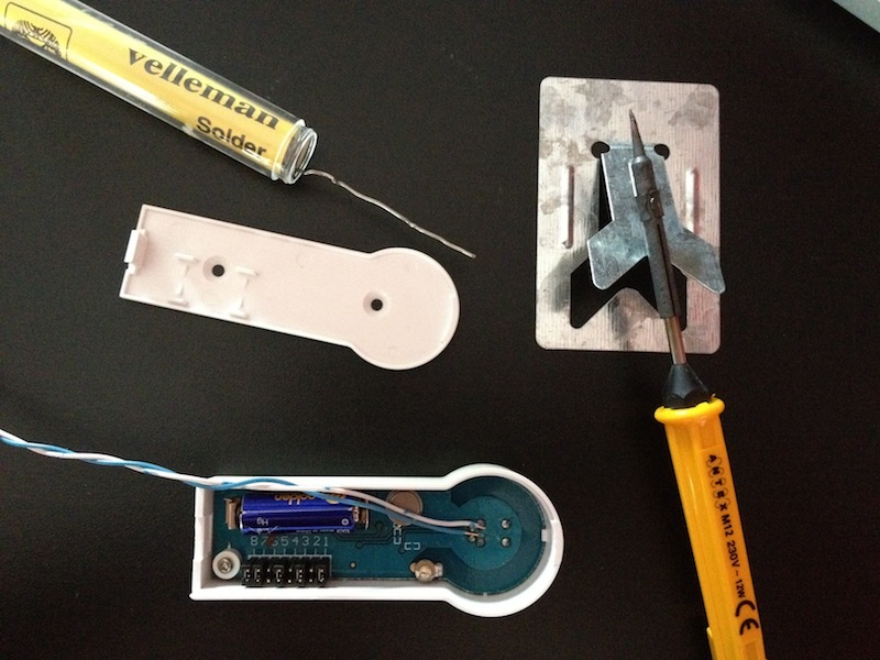
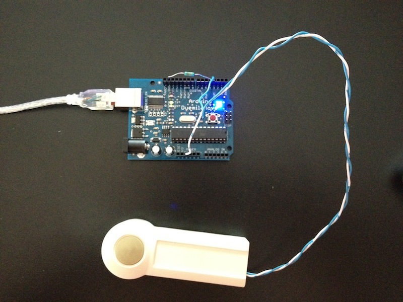
This project requires just a few parts, and because you're using a solderless breadboard and pre-cut jumper wires, you won't need any tools at all — except your computer and USB cable to connect the Arduino.
Connect digital input/output (I/O) pin 2 on the Arduino to row 1 on the breadboard.Connect the 5V pin on the Arduino to row 2 on the breadboard, and connect a nearby ground (Gnd) pin to row 3.Find the Gnd (–), Vcc (+), and Out pins on the PIR sensor.Plug the PIR sensor into the breadboard so that its (–) pin connects to the Gnd row, its (+) pin connects to 5V, and its Out pin connects to digital pin 2. connect a 10k resistor between PIR output pin and vcc.


Plug the LED's anode (the longer leg) into digital pin 13 on the Arduino.Plug the LED's cathode (the shorter leg, and/or the leg on the flattened side of the LED base) into the adjacent ground (Gnd) pin on the Arduino.Connect the buzzer's red wire to the Arduino's digital pin 10.Connect the buzzer's black wire to the Arduino's Gnd pin (there's a spare one on the Power block of pins).NOTE: These two wires can be reversed, as the polarity of the buzzer doesn't matter.
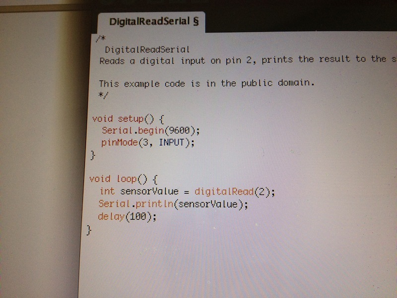
Code

int ledPin = 13;                // choose the pin for the LED
int inputPin = 2;               // choose the input pin (for PIR sensor)
int pirState = LOW;             // we start, assuming no motion detected
int val = 0;                    // variable for reading the pin status
int pinSpeaker = 10;           //Set up a speaker on a PWM pin (digital 9, 10, or 11)

void setup() {
  pinMode(ledPin, OUTPUT);      // declare LED as output
  pinMode(inputPin, INPUT);     // declare sensor as input
  pinMode(pinSpeaker, OUTPUT);
  Serial.begin(9600);
}

void loop(){
  val = digitalRead(inputPin);  // read input value
  if (val == HIGH) {            // check if the input is HIGH
    digitalWrite(ledPin, HIGH);  // turn LED ON
    playTone(300, 160);
    delay(150);

    
    if (pirState == LOW) {
      // we have just turned on
      Serial.println("Motion detected!");
      // We only want to print on the output change, not state
      pirState = HIGH;
    }
  } else {
      digitalWrite(ledPin, LOW); // turn LED OFF
      playTone(0, 0);
      delay(300);    
      if (pirState == HIGH){
      // we have just turned of
      Serial.println("Motion ended!");
      // We only want to print on the output change, not state
      pirState = LOW;
    }
  }
}
// duration in mSecs, frequency in hertz
void playTone(long duration, int freq) {
    duration *= 1000;
    int period = (1.0 / freq) * 1000000;
    long elapsed_time = 0;
    while (elapsed_time < duration) {
        digitalWrite(pinSpeaker,HIGH);
        delayMicroseconds(period / 2);
        digitalWrite(pinSpeaker, LOW);
        delayMicroseconds(period / 2);
        elapsed_time += (period);
    }
}

Upload the code to the arduino and test it.
Enjoy!!!!!!

iPhone Arduino Push Notification

This project will help you to hack your doorbell to send Push notification and an email with an attached picture when somebody’s at the door. It use the free PushingBox service to delegate all the programming part and make things easy.

How does it work

  • 1. When the doorbell is pushed, the Arduino sends an HTTP request to the PushingBox API.
  • 2. PushingBox launches the user's scenario and gets a picture from the web camera.
  • 3. PushingBox sends a Push notification to the user's phone and a mail message with the picture attached.

Notifying Doorbell with PushingBox


Notifying Doorbell with PushingBox
  • Open your doorbell.
  • Solder wires to the button's terminals.
  • Close the doorbell.

Notifying Doorbell with PushingBox
  • Plug the wires into the Arduino.
  • One wire on the 5v pin;
  • One wire on the 3rd input pin;
  • The 10K resistor between GND and the 3rd pin.

Notifying Doorbell with PushingBox
  • Test the connectivity with a simple Arduino program.

Notifying Doorbell with PushingBox
  • The hardware part is finished. Let's define the way you will be notified.
  • Go to http://www.pushingbox.com.
  • Login with your Google account.
  • Go to the My Services page.
  • Click on Add a service.

Notifying Doorbell with PushingBox
  • Click on the service by which you want be notified.
  • Use Prowl or Pushme.to for iPhone Push notification;
  • Notifry for Android Push notification;
  • Toasty for Windows Phone Push notification.
  • Enter the name of your new service and fill in the API that this application gave you when you installed it.
  • Click Submit.

Notifying Doorbell with PushingBox
  • Now, go to the My Scenarios page.
  • Create a scenario called "Somebody's at the door".
  • Click on Create scenario.
  • Click on Add an Action.

Notifying Doorbell with PushingBox          First, add an action using the Email Service.
  • Fill in the mail Subject and the Body.
  • The third field is optional and is for attaching a shot from your IP camera to the email. Fill in the URL (publicly reachable) of your web camera. The camera's output must be a picture less than 100KB in size.
  • Do the same with your Push notification service and click the Back button.

Notifying Doorbell with PushingBox
  • Your scenario is now created.
  • Click on "Test" to test the scenario.
  • You should receive a Push notification on your phone and an email.
  • Make a note of the "DeviceID" value of this scenario. You will paste it into the Arduino code.

Notifying Doorbell with PushingBox
  • Download the Arduino source code from the PushingBox API page and open it.
  • In the #define DEVID1 line, paste the DeviceID of your scenario. Make sure you enclose it in quotes as shown.
  • Compile the code and program your Arduino.
  • You're done! Test it

Arduino Stepper motor Control

Stepper motors fall somewhere in between a regular DC motor and a servo motor. They have the advantage that they can be positioned accurately, moved forward or backwards one 'step' at a time, but they can also rotate continuously.
The stepper motor has five leads, and we will be using both halves of the L293D this time. This means that there are a lot of connections to make on the breadboard.
The motor has a 5-way socket on the end. Push jumper wires into the sockets to allow the motor to be connected to the breadboard.
Note that the red lead of the Stepper motor is not connected to anything.
fritzing.jpg
The following sketch uses the Serial Monitor, so once the sketch is installed and running, open the Serial Monitor and enter a number of 'steps'. Try a value of about 500, this should cause the motor to turn through about 360 degrees. Enter -500 and it will turn back in the reverse direction.

Code

#include <Stepper.h>

int in1Pin = 12;
int in2Pin = 11;
int in3Pin = 10;
int in4Pin = 9;

Stepper motor(768, in1Pin, in2Pin, in3Pin, in4Pin);  

void setup()
{
  pinMode(in1Pin, OUTPUT);
  pinMode(in2Pin, OUTPUT);
  pinMode(in3Pin, OUTPUT);
  pinMode(in4Pin, OUTPUT);

  // this line is for Leonardo's, it delays the serial interface
  // until the terminal window is opened
  while (!Serial);
  
  Serial.begin(9600);
  motor.setSpeed(20);
}

void loop()
{
  if (Serial.available())
  {
    int steps = Serial.parseInt();
    motor.step(steps);
  }
}

In this tutorial, we do not use the common Red connection. This connection is only provided if you are using a different type of drive circuit that does not allow the current in each coil to be reversed. Having a center connection to each coil means that you can either energise the left or right side of the coil, and get the effect of reversing the current flow without having to use a circuit that can reverse the current.
Since we are using a L293D that is very good at reversing the current, we do not need this common connection, we can supply current in either direction to the whole of each of the coils.

Arduino servo Control

The servo motor has three leads. The color of the leads varies between servo motors, but the red lead is always 5V and GND will either be black or brown. The other lead is the control lead and this is usually orange or yellow. This control lead is connected to digital pin 9.
The servo is conveniently terminated in a socket into which we can push jumper wires, to link it to the breadboard and then to the Arduino.
fritzing_sweep.jpg

If servo Misbehaves

Your servo may behave erratically, and you may find that this only happens when the Arduino is plugged into certain USB ports. This is because the servo draws quite a lot of power, especially as the motor is starting up, and this sudden high demand can be enough to drop the voltage on the Arduino board, so that it resets itself.
If this happens, then you can usually cure it by adding a high value capacitor (470uF or greater) between GND and 5V on the breadboard.
The capacitor acts as a reservoir of electricity for the motor to use, so that when it starts, it takes charge from the capacitor as well as the Arduino supply.
The longer lead of the capacitor is the positive lead and this should be connected to 5V. The negative lead is also often marked with a '-' symbol.
Load up the following sketch onto your Arduino. You should find that the servo immediately begins to turn first in one direction and then back in the other.
The sketch is based on the standard 'sweep' sketch that you can find in the Arduino Examples under the folder 'servo'.


#include <Servo.h> 

int servoPin = 9;
Servo servo;  
int angle = 0;   // servo position in degrees 
void setup() 
  servo.attach(servoPin); 
 void loop() 
  // scan from 0 to 180 degrees
  for(angle = 0; angle < 180; angle++)  
  {                                  
    servo.write(angle);               
    delay(15);                   
  } 
  // now scan back from 180 to 0 degrees
  for(angle = 180; angle > 0; angle--)    
  {                                
    servo.write(angle);           
    delay(15);       
  } 

Servo motors are controlled by a series of pulses and to make it easy to use them, an Arduino library has been created so that you can just instruct the servo to turn to a particular angle.

Arduino SERVO knob

You just need to add the pot and a lead from its slider to A0 on the Arduino

fritzing_knob.jpg


#include <Servo.h> 

int potPin = 0;  
int servoPin = 9;
Servo servo; 
 
void setup() 
  servo.attach(servoPin);  
 
void loop() 
  int reading = analogRead(potPin);     // 0 to 1023
  int angle = reading / 6;              // 0 to 180-ish
  servo.write(angle);  

There is now a second variable called 'potPin'.
To set the position of the servo, we take an analog reading from A0. This gives us a value of between 0 and 1023. Since the servo can only rotate through 180 degrees, we need to scale this down. Dividing it by six will give us an angle between 0 and 170, which will do just fine.

The position of the servo motor is set by the length of a pulse. The servo expects to receive a pulse roughly every 20 milliseconds. If that pulse is high for 1 millisecond, then the servo angle will be zero, if it is 1.5 milliseconds, then it will be at its centre position and if it is 2 milliseconds it will be at 180 degrees.The end points of the servo can vary and many servos only turn through about 170 degrees. You can also buy 'continuous' servos that can rotate through the full 360 degrees.

Thursday 29 August 2013

Raspberry Pi

The Raspberry Pi is a single-board computer developed in the UK by the Raspberry Pi Foundation with the intention of stimulating the teaching of basic computer science in schools. The Raspberry Pi is a credit-card sized computer that plugs into your TV and a keyboard. It’s a capable little PC which can be used for many of the things that your desktop PC does, like spreadsheets, word-processing and games. It also plays high-definition video. The design is based around a Broadcom BCM2835 SoC, which includes an ARM1176JZF-S 700 MHz processor, VideoCore IV GPU, and 128 or 256 Megabytes of RAM. The design does not include a built-in hard disk or solid-state drive, instead relying on an SD card for booting and long-term storage. This board is intended to run Linux kernel based operating systems.

Raspberry Pi Model B 512MB RAM
Raspberry Pi

Tuesday 20 August 2013

Power Supply for Breadboard

Embedded systems require electric power to operate. Most of the components in them including the processors can operate at a wide range of voltages. For example, the operating voltage range for PIC16F688 is from 2 to 5.5 V. It means you can supply power from three AA size batteries (4.5 V) and it will work just fine as long as the battery voltage doesn’t fall below 2 V. But there are certain applications where you need a regulated constant voltage for safer operation of the embedded system. For instance, any application that uses analog-to-digital converters (ADCs). ADCs require a fixed reference voltage to provide accurate digital count for input analog signal. If the reference voltage is not stable, the ADC output is meaningless. So, today we are going to make a regulated +5V power source for our lab.
An LM7805 linear regulator IC is used for this purpose. It converts a DC input voltage of range 7-25 V to a stable +5 V. It requires just two external capacitors and is very easy to use, as shown below.
The input DC voltage for LM7805 could be obtained from a 9V DC wall adapter that can supply 1 Amp of load current. Actually, 12 to 24 V adapter will work too, but the LM7805 regulator dissipates an extreme amount of heat energy at higher input voltages and, therefore, requires a bulky heat sink. The wall adapter is chosen because it is cheap, easily available (you might already have got a spare one at home), and safe (the high voltage mains AC is isolated). You can solder this circuit on a general purpose prototyping board.

Radio Frequency(RF) Module

This example uses HT12E/D encoder-decoder pair for converting the parallel data to serial and back.


This encoder-decoder pair supports 4 bit parallel data.The circuit has two parts transmitter and receiver. In the transmitter part we are using HT12E for encoding data from parallel to serial. The serial output from the from the encoder is fed to the data IN of the RF transmitter. Four switches namely SW0,SW1,SW2,SW3 are used to input data to the decoder. These switches are pushbutton switches with active low states.(i.e.when you press it, the data input will be '0' and in the released state data input will be '1'. The default state is '1').

At the receiver section we are having RF receiver and HT12D decoder IC. The serial data from the receiver is fed into to serial input of the decoder. The parallel data is displayed with the help of LED's .

Another LED at the pin VT of the decoder shows whether your link is established or not. If it is ON then everything is OK. Instead if it is permanently OFF, then there is a link failure. You may refer the data sheet of the IC to know the  exact function of pin VT. After each successful transmission of a 4-bit data, VT pin goes to a low state for a while and will come back to high state. Thus during the transmission you may see the LED at pin VT blinking.

Troubleshooting:

If your circuit is not working, just remove the RF transmitter and receiver and make a wired connection from the serial data OUT of the HT12E encoder to the serial data IN of the HT12D decoder. Now check whether you could receive the data send from the encoder to decoder. If it is not working, you can conclude that problem is with the encoder/decoder pair. Either there will be some bugs in the circuit or your IC's might be damaged ones.

Monday 19 August 2013

L293D Motor Driver

Generally, even the simplest robot requires a motor to rotate a wheel or performs particular action. Motor Control using NPN Transistor
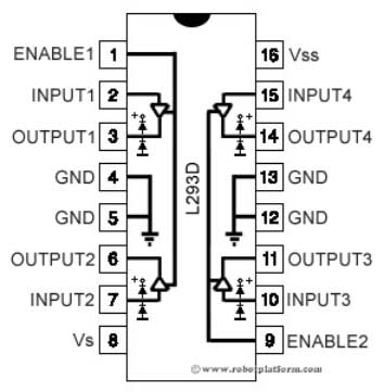
Since motors require more current then the microcontroller pin can typically generate, you need some type of a switch (Transistors, MOSFET, Relay etc.,) which can accept a small current, amplify it and generate a larger current, which further drives a motor. This entire process is done by what is known as a motor driver.
Motor driver is basically a current amplifier which takes a low-current signal from the microcontroller and gives out a proportionally higher current signal which can control and drive a motor. In most cases, a transistor can act as a switch and perform this task which drives the motor in a single direction.
Turning a motor ON and OFF requires only one switch to control a single motor in a single direction. What if you want your motor to reverse its direction? The simple answer is to reverse its polarity. This can be achieved by using four switches that are arranged in an intelligent manner such that the circuit not only drives the motor, but also controls its direction. Out of many, one of the most common and clever design is a H-bridge circuit where transistors are arranged in a shape that resembles the English alphabet "H".H-bridge
As you can see in the image, the circuit has four switches A, B, C and D. Turning these switches ON and OFF can drive a motor in different ways.
  1. Turning on Switches A and D makes the motor rotate clockwise
  2. Turning on Switches B and C makes the motor rotate anti-clockwise
  3. Turning on Switches A and B will stop the motor (Brakes)
  4. Turning off all the switches gives the motor a free wheel drive
  5. Lastly turning on A & C at the same time or B & D at the same time shorts your entire circuit. So, do not attempt this.
H-bridges can be built from scratch using relays, mosfets, field effect transistors (FET), bi-polar junction transistors (BJT), etc. But if your current requirement is not too high and all you need is a single package which does the job of driving a small DC motor in two directions, then all you need is a L293D IC. This single inexpensive package can interface not one, but two DC motors. L293, L293B and few other versions also does the same job, but pick the L293D version as this one has an inbuilt flyback diode which protects the driving transistors from voltage spikes that occur when the motor coil is turned off.

Introduction to L293D ICL293D Skeleton
L293D IC generally comes as a standard 16-pin DIP (dual-in line package). This motor driver IC can simultaneously control two small motors in either direction; forward and reverse with just 4 microcontroller pins (if you do not use enable pins). Some of the features (and drawbacks) of this IC are:
  1. Output current capability is limited to 600mA per channel with peak output current limited to 1.2A (non-repetitive). This means you cannot drive bigger motors with this IC. However, most small motors used in hobby robotics should work. If you are unsure whether the IC can handle a particular motor, connect the IC to its circuit and run the motor with your finger on the IC. If it gets really hot, then beware... Also note the words "non-repetitive"; if the current output repeatedly reaches 1.2A, it might destroy the drive transistors.
  2. Supply voltage can be as large as 36 Volts. This means you do not have to worry much about voltage regulation.
  3. L293D has an enable facility which helps you enable the IC output pins. If an enable pin is set to logic high, then state of the inputs match the state of the outputs. If you pull this low, then the outputs will be turned off regardless of the input states
  4. The datasheet also mentions an "over temperature protection" built into the IC. This means an internal sensor senses its internal temperature and stops driving the motors if the temperature crosses a set point
  5. Another major feature of L293D is its internal clamp diodes. This flyback diode helps protect the driver IC from voltage spikes that occur when the motor coil is turned on and off (mostly when turned off)
  6. The logical low in the IC is set to 1.5V. This means the pin is set high only if the voltage across the pin crosses 1.5V which makes it suitable for use in high frequency applications like switching applications (upto 5KHz)
  7. Lastly, this integrated circuit not only drives DC motors, but can also be used to drive relay solenoids, stepper motors etc.
L293D Connections
The circuit shown to the right is the most basic implementation of L293D IC. There are 16 pins sticking out of this IC and we have to understand the functionality of each pin before implementing this in a circuit
  1. Pin1 and Pin9 are "Enable" pins. They should be connected to +5V for the drivers to function. If they pulled low (GND), then the outputs will be turned off regardless of the input states, stopping the motors. If you have two spare pins in your microcontroller, connect these pins to the microcontroller, or just connect them to regulated positive 5 Volts.
  2. Pin4, Pin5, Pin12 and Pin13 are ground pins which should ideally be connected to microcontroller's ground.
  3. Pin2, Pin7, Pin10 and Pin15 are logic input pins. These are control pins which should be connected to microcontroller pins. Pin2 and Pin7 control the first motor (left); Pin10 and Pin15 control the second motor(right).
  4. Pin3, Pin6, Pin11, and Pin14 are output pins. Tie Pin3 and Pin6 to the first motor, Pin11 and Pin14 to second motor
  5. Pin16 powers the IC and it should be connected to regulated +5Volts
  6. Pin8 powers the two motors and should be connected to positive lead of a secondary battery. As per the datasheet, supply voltage can be as high as 36 Volts.
Truth table
I have shown you where to connect the motors, battery and the microcontroller. But how do we control the direction of these motors? Let us take an example:
Suppose you need to control the left motor which is connected to Pin3 (O1) and Pin6 (O2). As mentioned above, we require three pins to control this motor - Pin1 (E1), Pin2 (I1) and Pin7 (I2). Here is the truth table representing the functionality of this motor driver.
Pin 1Pin 2Pin 7Function
HighHighLowTurn Anti-clockwise (Reverse)
HighLowHighTurn clockwise (Forward)
HighHighHighStop
HighLowLowStop
LowXXStop
High ~+5V, Low ~0V, X=Either high or low (don't care)
In the above truth table you can observe that if Pin1 (E1) is low then the motor stops, irrespective of the states on Pin2 and Pin7. Hence it is essential to hold E1 high for the driver to function, or simply connect enable pins to positive 5 volts.
With Pin1 high, if Pin2 is set high and Pin7 is pulled low, then current flows from Pin2 to Pin7 driving the motor in anti-clockwise direction. If the states of Pin2 and Pin7 are flipped, then current flows from Pin7 to Pin2 driving the motor in clockwise direction.
The above concept holds true for other side of the IC too. Connect your motor to Pin11 and Pin14; Pin10 and Pin15 are input pins, and Pin9 (E2) enables the driver.
I guess we have already had too much of theory. In the next section, we will start building the board.

Operational Amplifier (Op-amps)

An op-amp operates on analog input. It can be used to amplify or attenuate this input, and to carry out mathematical operations such as addition, subtraction, integration, and differentiation. Because of their wide range of uses, op-amps are encountered in most electric circuits.

Figure 1: Op-amp Circuit


A typical op-amp, is equipped with a non-inverting input (Vin (+)), an inverting input (Vin (−)), and an output (Vout). Although not shown in the diagram, an op-amp also has two power inputs (positive and negative), and may also include an offset input and other terminals.
The fundamental function of an op-amp is to greatly amplify the differential between the two inputs, and output the result. If input at V(+) is greater than at V(−), the op-amp will amplify and output a positive signal; if V(−) is greater, the op-amp will output an amplified negative signal. Two other features of a typical op-amp are: (a) the input impedance is extremely high, and (b) the output impedance is extremely low.
Because the op-amp's gain is so high, even small differences in the inputs will rapidly drive the output voltage to its maximum or minimum value. For this reason, op-amps are usually connected to a negative feedback. Let's look at an example.

Op-Amp :- Inverting amplifier

Figure. 2: Inverting Amplifier Circuit
The circuit amplifies and inverts (reverses the phase of) the input signal, and outputs the result. The circuit uses negative feedback: some of the output signal is inverted and returned to the input. In this example, feedback occurs because output Vout is connected through resistor R2 to the inverting input (−).
Let's look at how this circuit works. If the output is not connected to a power voltage, then the voltages applied to the inverting (−) and non-inverting (+) inputs are equal; the two inputs act as if shorted together; we can envision an imaginary short. Since the voltage difference between this imaginary short and the non-inverting input is 0 V, point A will also be at 0 V. By Ohm's Law, then, we have I1 = Vin/R1.
Because op-amps have extremely high input impedance, there is virtually no current flow into the inverting input (−). Accordingly, I1 flows through point A and R2; this means that I1 and I2 are virtually equal. Then, by Ohm's Law, we have Vout = −I1 × R2, where I1 is negative because I2 flows from point A, where the voltage is 0. Looking at this in another way: any attempt to raise the input voltage at the inverting input (−) produces inverted and highly amplified output voltage that flows backward, passing through R2 and connecting to the inverted input terminal (−), thereby suppressing the voltage rise at this terminal. The system stabilizes at the output voltage that brings the voltage at the inverting input (−) to 0 V, equivalent to the voltage at the non-inverting input.
Next, let's see how we can use the relationship between input and output to find the op-amp's gain. Specifically, Vout/Vin = (−I1 × R2) / (I1 × R1) = −R2/R1. The gain is negative because the output waveform phase is opposite that of the input waveform. 
An important thing to note about the above equation is that the gain is entirely determined by the ratio of resistances R2 and R1. Accordingly, you can change the gain simply by changing the resistances. So while the op-amp itself has a high gain, appropriate use of negative feedback can reduce the actual amplification to the desired level.

Op-Amp:- Non-Inverting Amplifier

Figure. 3: Non-inverting Amplifier Circuit
In the previous section we saw how an op-amp can be used to implement an inverting amplifier. Figure shows how we can use it to make a non-inverting amplifier. The non-inverting amp differs from the inverting one in two major ways: (1) the output waveform is in phase with the input waveform, and (2) the input goes into the non-inverting input terminal (+). But note that non-inverting and inverting circuits both make use of negative feedback.
So how does this circuit work? We still have the imaginary short, which means that the non-inverting (+) and inverting (−) inputs are both at voltage Vin. So point A is also at Vin. Ohm's Law tells us that the voltage at R1 is Vin = R1 × I1. And since there is essentially no current into either of the op-amp inputs, it follows that I1 = I2. And as Vout is the sum of voltages at R1 and R2, we know that Vout= R2 × I2 + R1 × I1. We can rearrange these expressions to find the gain G, like this: G = Vout/Vin = (1 + R2/R1)
Because this amplifier preserves the phase, it is often found in applications where phase considerations are an issue.
Note also that if R1 is removed from the circuit and R2 is set to 0 ohm (or shorted), the circuit becomes a voltage follower with a gain of 1. This type of circuit is often used in buffering circuitry and impedance conversion circuits.

Comparator Circuit

Figure 4: Comparator Circuit
A comparator circuit compares two voltages and outputs either a 1 (the voltage at the plus side; VDD in the illustration) or a 0 (the voltage at the negative side) to indicate which is larger. Comparators are often used, for example, to check whether an input has reached some predetermined value. In most cases a comparator is implemented using a dedicated comparator IC, but op-amps may be used as an alternative. Comparator diagrams and op-amp diagrams use the same symbols.
Figure 4 shows a comparator circuit. Note first that the circuit does not use feedback. The circuit amplifies the voltage difference between Vin and VREF, and outputs the result at Vout. If Vin is greater than VREF, then voltage at Vout will rise to its positive saturation level; that is, to the voltage at the positive side. If Vin is lower than VREF, then Vout, will fall to its negative saturation level, equal to the voltage at the negative side.


Digital Thermometer

This tutorial shows an interesting way to read the temperature from the environment with the Arduino, and shows it on a LCD 16x2 display (in Fahrenheit), by using some elements from its programming and the temperature LM35DZ sensor.
For that, it will be necessary the following components:
- 1 Arduino board
- 1 LCD 16x2 display
- 1 10K potentiometer
- 1 Temperature LM35 sensor
- Jumpers for connection
This sensor captures the external temperature and converts it into a corresponding voltage value. In this circuit, we connect the output Vo of the sensor to the Arduino’s A0 pin, which converts it to a float value of temperature, and then, exhibits it on the LCD. The 10K potentiometer adjusts the contrast of the display.

Now, set up the circuit below with the Arduino and the other components:  
And then, open the Arduino’s IDE and enter the following code:

#include  <LiquidCrystal.h>         // Include the library to use a LCD display
#define          sensor           0        // Define the A0 pin as “sensor”

int  Vin;           //  Variable to read the value from the Arduino’s pin
float  Temperature; //  Variable that receives the converted voltage value to temperature
float     TF;   // Variable to receive the converted value from  ºC to ºF

LiquidCrystal  lcd    (12, 11, 5, 4, 3, 2); 
/* The function above declares which Arduino’s pins will be used for controlling the LCD */
void  setup()
{
  lcd.begin(16, 2);                            //  It tells the Arduino that the display is a 16x2 type
  lcd.print("Temperature: ");           //  Send the text to the screen of the display.
}
void  loop()
{
  Vin = analogRead (sensor);  /*   Tells the Arduino to read the pin and stores the value in “Vin” */
  Temperature=(500*Vin)/1023;  /* Converts the voltage value into temperature and stores it into the “Temperature”  variable  (in  ºC)*/
TF = ((9*Temperature)/5)+32; // Converts  ºC to ºF
  lcd.setCursor(0, 1);           // Moves  the cursor of the display to the next line
  lcd.print(TF);    // Exhibits the value of the temperature on the display
  lcd.print(" F");         // Writes “F” to indicate that it is in Fahrenheit scale.

  delay(1000);  //  Waits for a second to read the pin again
}
In the end, upload the code to your Aduino.
Your project to show the temperature is ready!!! We hope you have enjoyed. Any doubts, post here.
Note: The LM35DZ sensor converts temperature values from -55ºC to 150ºC.
If somebody is interested, this is the explanation for the conversion calculation from voltage to temperature done by the software.
In this sensor, for each 1ºC received, the Vo output is added in 10mV, in a range from 0 to 5V, with 10 bits of resolution for Analog/Digital conversion (1024 different values to represent the temperature).
Thus, the maximum value (1023, therefore it is from 0 to 1023) will be 5V. The half will match 511 or 2.5V, and so forth. For calculation purposes, there would be 5V in the output of the sensor for a temaprature value of 500ºC (which is different in a real situation). However, this regard lets us generalize it to the following relation:
Temperature  ----- Vin
         500ºC  ----- 1023              (maximum values)

So, there will be:
Temperature = (500*Vin)/1023, but as it is in ºC and we want in ºF, we convert it:
TF = ((9*Temperature)/5)+32, and this is the printed value on the LCD display.