In this simple project, we’ll build a motion-sensing alarm using a PIR (passive infrared) sensor and an Arduino microcontroller. This is a great way to learn the basics of using digital input (from the sensor) and output (in this case, to a noisy buzzer) on your Arduino.
This project requires just a few parts, and because you're using a solderless breadboard and pre-cut jumper wires, you won't need any tools at all — except your computer and USB cable to connect the Arduino.
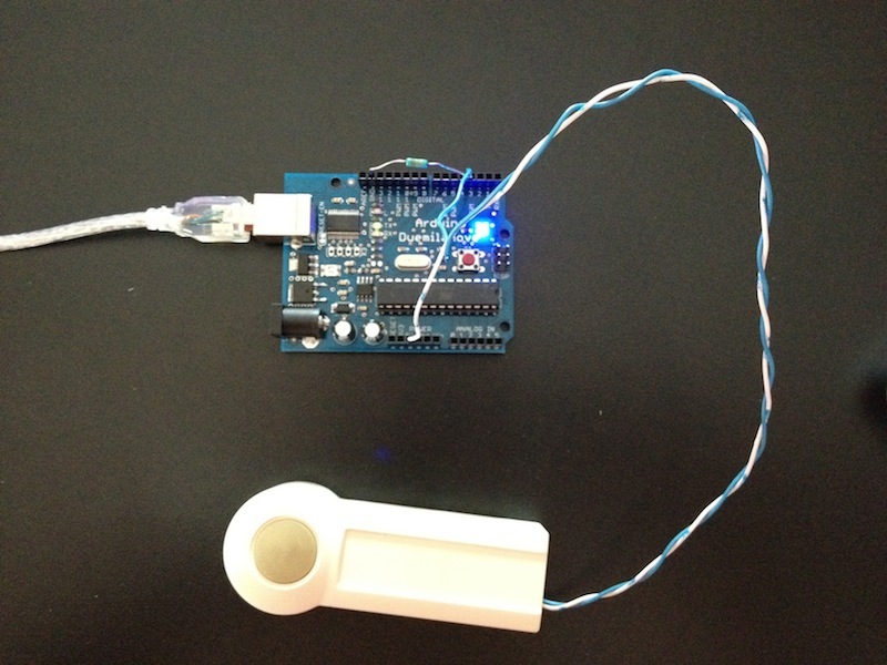
Connect digital input/output (I/O) pin 2 on the Arduino to row 1 on the breadboard.Connect the 5V pin on the Arduino to row 2 on the breadboard, and connect a nearby ground (Gnd) pin to row 3.Find the Gnd (–), Vcc (+), and Out pins on the PIR sensor.Plug the PIR sensor into the breadboard so that its (–) pin connects to the Gnd row, its (+) pin connects to 5V, and its Out pin connects to digital pin 2. connect a 10k resistor between PIR output pin and vcc.

Plug the LED's anode (the longer leg) into digital pin 13 on the Arduino.Plug the LED's cathode (the shorter leg, and/or the leg on the flattened side of the LED base) into the adjacent ground (Gnd) pin on the Arduino.Connect the buzzer's red wire to the Arduino's digital pin 10.Connect the buzzer's black wire to the Arduino's Gnd pin (there's a spare one on the Power block of pins).NOTE: These two wires can be reversed, as the polarity of the buzzer doesn't matter.
Code
int ledPin = 13;                // choose the pin for the LED
int inputPin = 2;               // choose the input pin (for PIR sensor)
int pirState = LOW;             // we start, assuming no motion detected
int val = 0;                    // variable for reading the pin status
int pinSpeaker = 10;           //Set up a speaker on a PWM pin (digital 9, 10, or 11)

void setup() {
  pinMode(ledPin, OUTPUT);      // declare LED as output
  pinMode(inputPin, INPUT);     // declare sensor as input
  pinMode(pinSpeaker, OUTPUT);
  Serial.begin(9600);
}

void loop(){
  val = digitalRead(inputPin);  // read input value
  if (val == HIGH) {            // check if the input is HIGH
    digitalWrite(ledPin, HIGH);  // turn LED ON
    playTone(300, 160);
    delay(150);


    if (pirState == LOW) {
      // we have just turned on
      Serial.println("Motion detected!");
      // We only want to print on the output change, not state
      pirState = HIGH;
    }
  } else {
      digitalWrite(ledPin, LOW); // turn LED OFF
      playTone(0, 0);
      delay(300);
      if (pirState == HIGH){
      // we have just turned of
      Serial.println("Motion ended!");
      // We only want to print on the output change, not state
      pirState = LOW;
    }
  }
}
// duration in mSecs, frequency in hertz
void playTone(long duration, int freq) {
    duration *= 1000;
    int period = (1.0 / freq) * 1000000;
    long elapsed_time = 0;
    while (elapsed_time < duration) {
        digitalWrite(pinSpeaker,HIGH);
        delayMicroseconds(period / 2);
        digitalWrite(pinSpeaker, LOW);
        delayMicroseconds(period / 2);
        elapsed_time += (period);
    }
}
Upload the code to the arduino and test it.
Enjoy!!!!!!